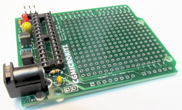
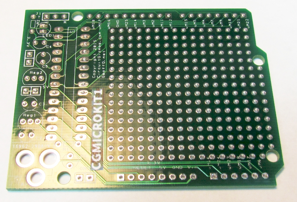
Assembly of the CGMICROKIT is easy! The kit contains the PCB:
And these parts:
From left to right, top to bottom the parts are on row 1 the console header and 28 pin socket for the CGMICROMITE2, row 2 the barrel jack, two voltage regulators, and LED, row 3 is a 330 ohm resistor, row 4 is a 10k ohm resistor, row 5 is the 22 uF capacitor and four .1 uF caps.
Step One:
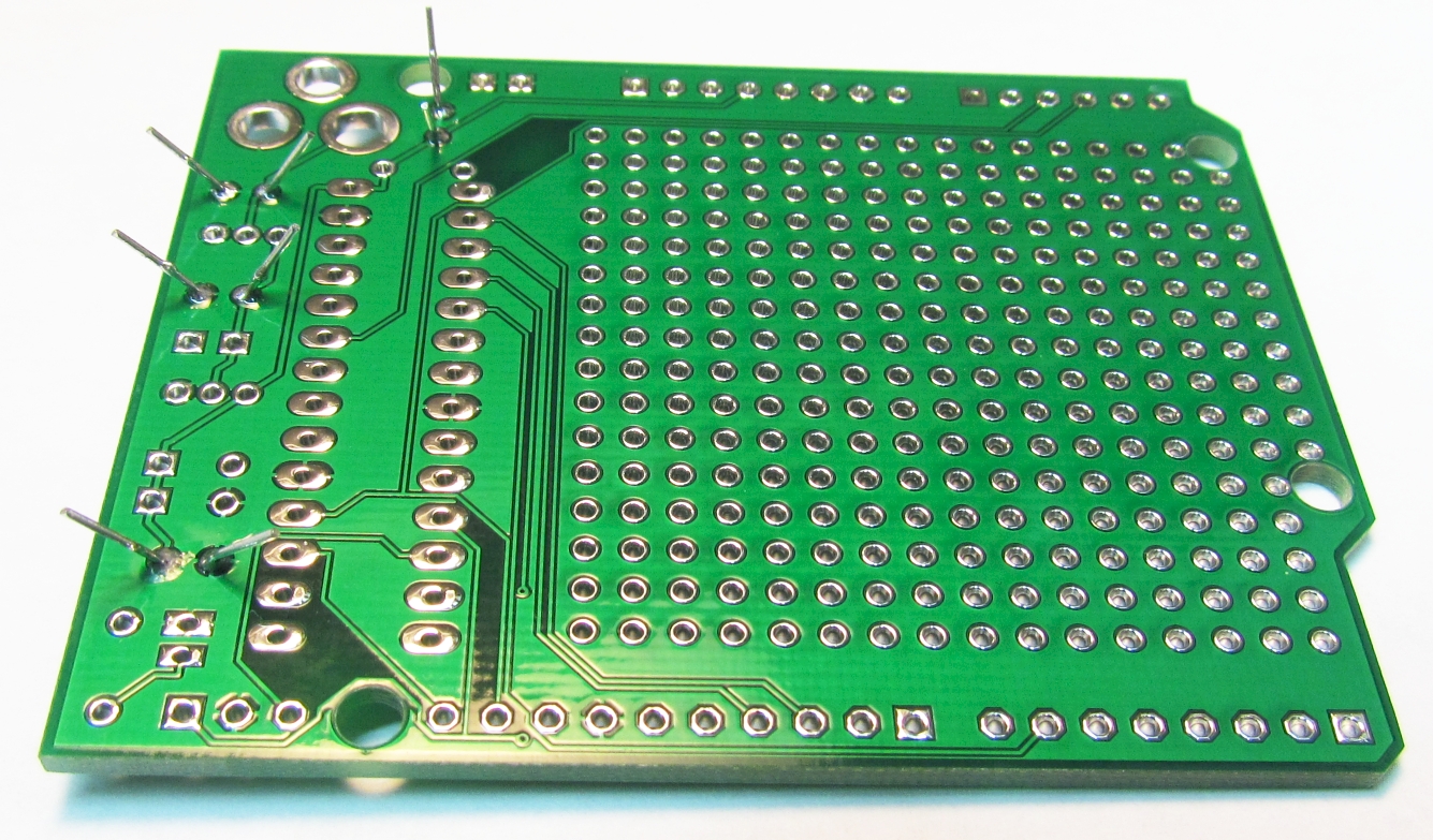
Insert and solder into place the .1 uF capacitors. With these and all remaining parts, trim the leads on the back side of the board after soldering.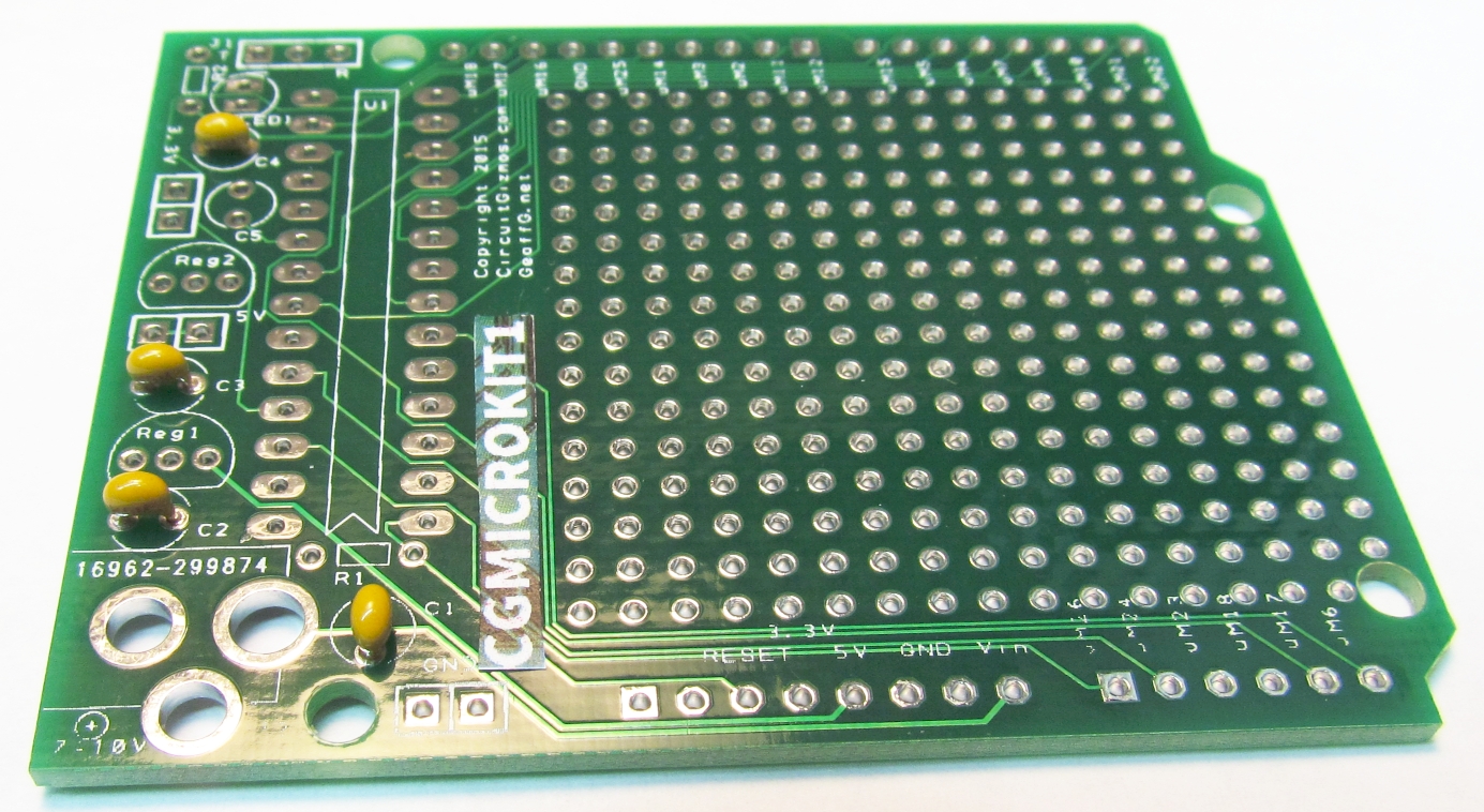
Step Two:
Insert and solder the two resistors. R1 is the 10k ohm, R2 is the 330 ohm.
Step Three:
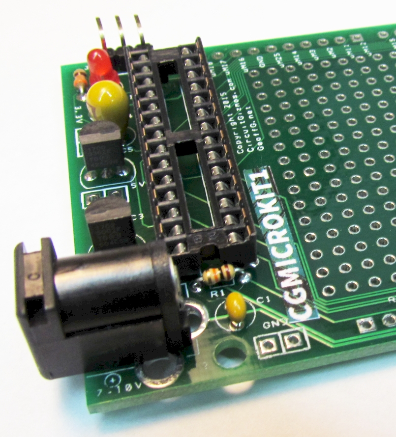
Identify the regulators. Reg1 is the 5V regulator, marked 1702 5002. Reg2 is the 3.3V regulator, marked 1700 3302. Insert and solder those in place with the orientation of the flat side of the regulator matching the flat part of the silk screen. See the photo for step four.
Step Four:
Insert the LED and the 22 uF capacitor. The LED has a flat side similar to the regulators. The 22 uF capacitor is polarized and should be inserted as depicted in the photo. Solder these parts in place. The console header can be left straight or the pins can be bent. It is soldered in next to the LED.
Step Five:
Solder in place the 28 pin chip socket and the barrel connector.
