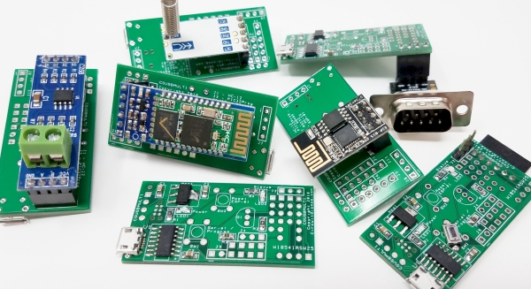
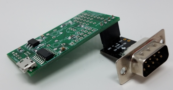
The CGUSBMULTI is a USB/serial controller for seven different types of serial module interfaces, both wired and wireless. The CGUSBMULTI appears as a USB serial port when plugged into a computer. Windows 10 has the drivers for the CGUSBMULTI built in. The CGUSBMULTI uses a USB micro cable.
The CGUSBMULTI can be used to provide a PC with RS232, RS485, TTL (3.3V), 433MHz, Bluetooth, and Wifi serial connections when paired with an appropriate module. Furthermore, the CGUSBMULTI can be used as an ISP for PIC32 programming.
Purchase the CGUSBMULTI here.
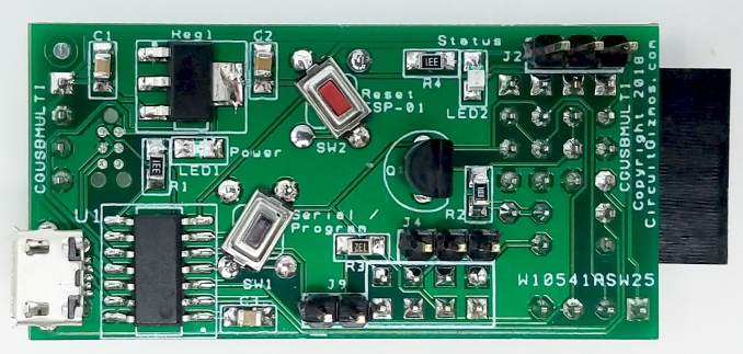
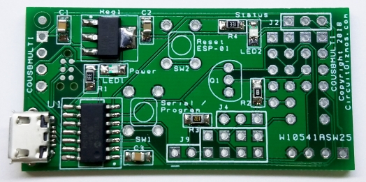
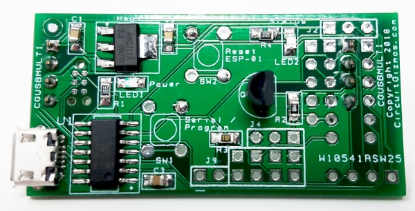
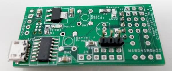
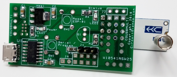
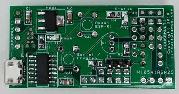
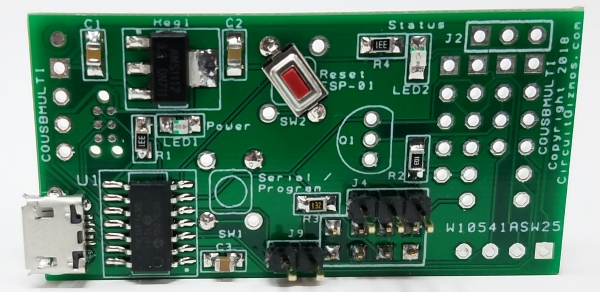
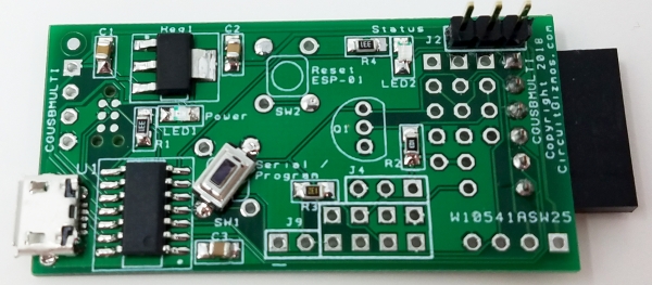
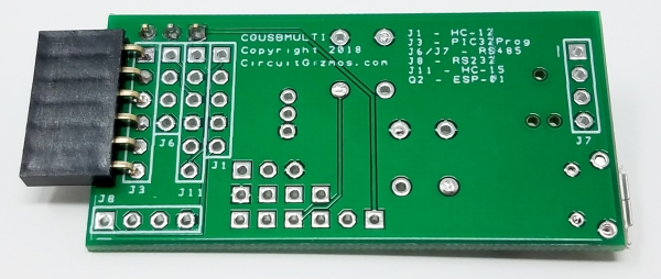
When fully populated, the CGUSBMULTI has a micro USB connector (bottom left of the image above) for connection to a PC. There are two buttons, two LEDs, and three pin jumpers.
LED1 is a red LED that indicates power, and also has alternate functions when the CGUSBMULTI is used as a PIC32 programmer.
LED2 is a green LED used when the CGUSBMULTI is connected to a WiFi module.
SW1, when present, has functions when the CGUSBMULTI is used as a PIC32 programmer.
SW2, when present, is a reset when the CGUSBMULTI is connected to a WiFi module.
When the pin headers are populated on the board, J9 is a power connector for the WiFi module, J4 is used with the WiFi module, the HC-12 (433MHz radio) module, and the HC-05 (Bluetooth) module.
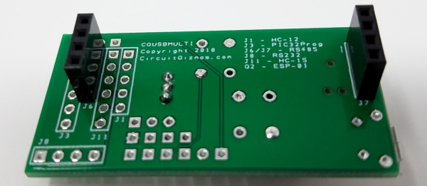
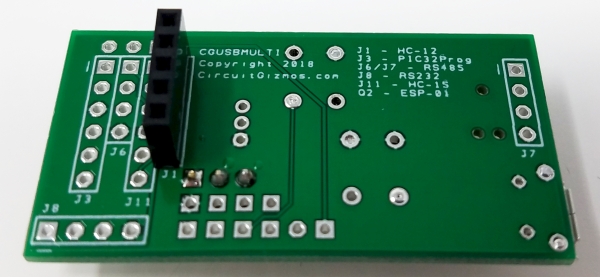
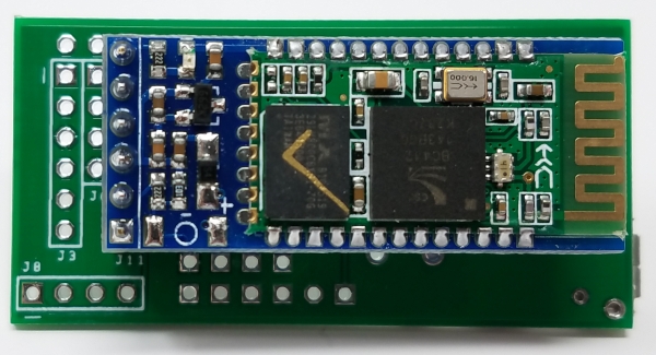
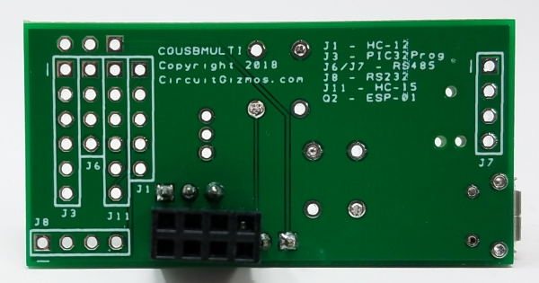
On the back side if the CGUSBMULTI are the headers for the various serial modules. When populated, these are the connections for the headers:
J1 – HC-12 433MHz radio module interface
J3 – PIC32 programming interface
J6/J7 – RS485 module interface
J8 – Rs232 module interface, TTL serial interface
J11 – HC-05/HC-06/HM-10 Bluetooth module interface
Q2 – ESP8266-01 WiFi module interface
CGUSBMULTI – RS232 Interface

To use the CGUSBMULTI as a USB to RS232 interface, the CGUSBMULTI is populated with a 4-pin female header at location J8. No other headers need to be populated on the board.
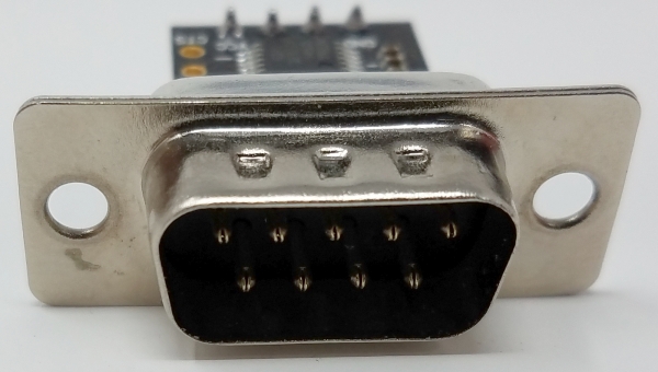
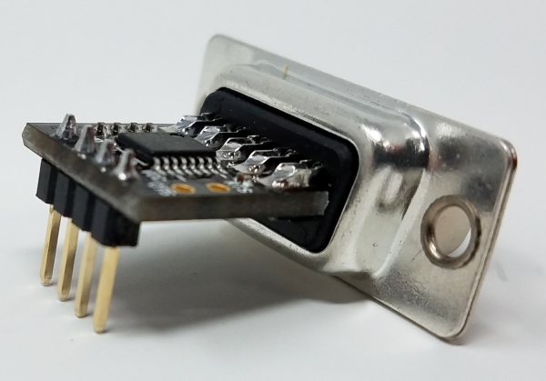
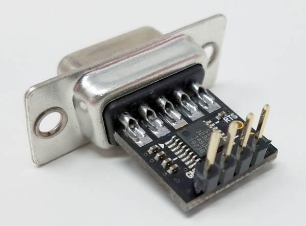

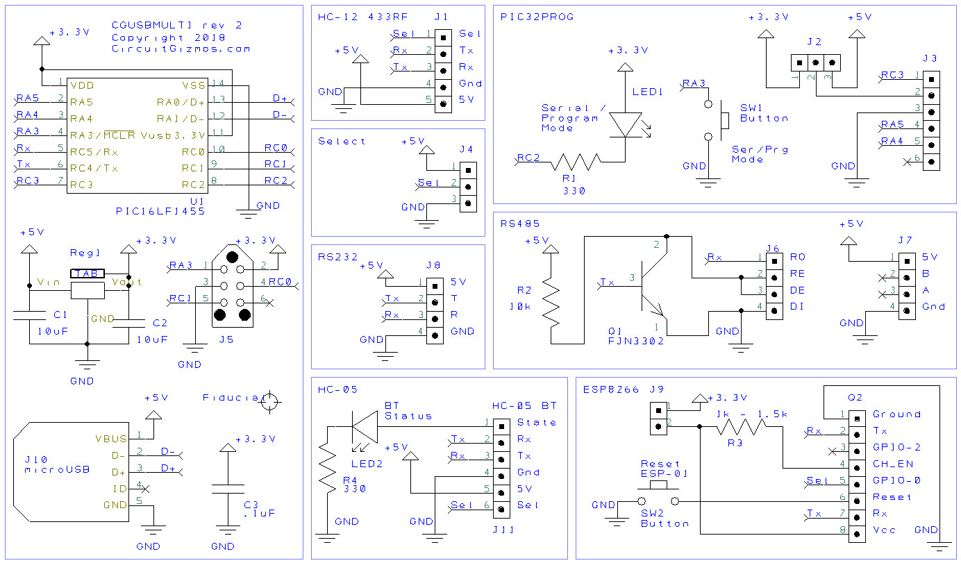
Pin 1 highlighted on the graphic is 5V, pin 2 is Tx (from the PC’s perspective), pin 3 is Rx, and pin 4 is ground. Please be sure to install the RS232 module with the correct orientation.
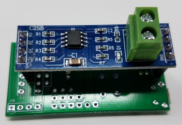
CGUSBMULTI – RS485 Interface
To use the CGUSBMULTI as a USB to RS485 interface, the CGUSBMULTI is populated with two 4-pin female headers at location J6 and J7, and a transistor at location Q1.
J6 pin 1 connects to the RS485 module RO, Pin 2 to RE, pin 3 to DE, and pin 4 to DI. J7 pin 1 connects to the RS485 module VCC (5V), pin 2 to B, pin 3 to A, and pin 4 to GND.
CGUSBMULTI – TTL (3.3V) Interface
To use the CGUSBMULTI as a USB to TTL serial interface, the CGUSBMULTI is populated with a 4-pin female header at location J8. No other headers need to be populated on the board.
Pin 1 highlighted on the graphic is 5V, pin 2 is Tx (from the PC’s perspective), pin 3 is Rx, and pin 4 is ground.
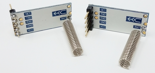
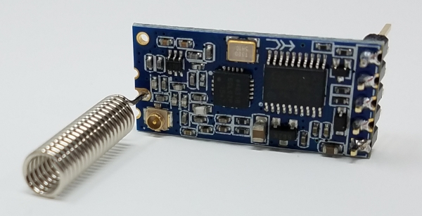
CGUSBMULTI – HC-12 (433MHz radio) Interface
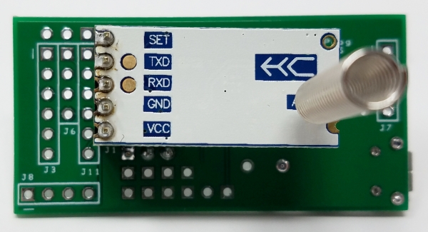
To use the CGUSBMULTI as a USB to HC-12 433MHz radio module, the CGUSBMULTI is populated with a 5-pin female header at location J1, and with a 3-pin male header at J4.
J1 pin 1 connects to the HC-12 433MHz module SET, pin 2 to TXD, pin 3 to RXD, pin 4 to GND, and pin 5 to VCC (5V).


The selection of ‘sel’ to low (0v) will set the HC-12 433MHz radio module SET line low (0v) to command mode where AT commands control the module.
CGUSBMULTI – HC-05/HC-06/HM-10 (Bluetooth) Interface

To use the CGUSBMULTI as a USB to HC-05/HC-06/HM-10 Bluetooth module, the CGUSBMULTI is populated with a 6-pin female header at location J11, and with a 3-pin male header at J4.
J11 pin 1 connects to the HC-05 Bluetooth module STATE, pin 2 to RXD, pin 3 to TXD, pin 4 to GND, pin 5 to VCC (5V), and pin 6 to WAKEUP.

The selection of ‘sel’ to high (5v) will set the HC-05 Bluetooth module KEY/WAKEUP line high (5v) to command mode where AT commands control the module.
CGUSBMULTI – WiFi (ESP8266-01) Interface
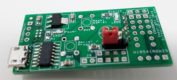
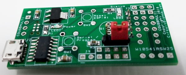
To use the CGUSBMULTI as a USB to ESP8266-01 WiFi module, the CGUSBMULTI is populated with a 2×4-pin female header at location Q2, with a 3-pin male header at J4, and a 2-pin male header at J9.
With J9 jumpered by a shorting block, the ESP8266-01 WiFi module is powered by the USB port of the PC. In some cases, a USB port cannot provide enough current for the ESP8266-01 WiFi module. With the shorting block removed pin 2 of J9 could be connected to an external 3.3V supply that can provide enough current for the ESP8266-01 WiFi module.
Q2 pin 1 connects to the ESP8266-01 WiFi module GND, pin 2 to TXD, pin 3 to GPIO-2, pin 4 to CH_EN (which is pulled high by a 1-1.5 k resistor), pin 5 to GPIO-0, pin 6 to the red reset button, pin 7 to RXD, and pin 8 to VCC (3.3V if J9 jumper in place).

The selection of ‘sel’ to high (5v) will likely damage the ESP8266-01 WiFi module. Do not set this line to 5V.
The selection of ‘sel’ to low (0v) will set the ESP8266-01 WiFi module GPIO-0 line low (0v) to command mode where AT commands control the module.
CGUSBMULTI – PIC32 ICSP Programming

J3 pin 1 connects to the target PIC32 ICSP reset, pin 2 to the target power, pin 3 to GND, pin 4 to PIC32 ICSP data, pin 5 to PIC32 ICSP clock, and pin 6 is connected to nothing.
CGUSBMULTI Schematic
For Windows 10, the driver for the CGUSBMULTI should be built in. For Windows XP SP3 or later use: Windows-Driver-for-CGUSBMULTI
To use the CGUSBMULTI for programming, the PIC32PROG GUI (credit to Robert Rozee) in this zip file works with pic32prog.exe to program PIC32 ICSP. PIC32PROG-and-GUI