PS/2 Keyboard Chip
| Quantity | Price per item | Discount |
| 10 items | $6.39 (USDollar) | 3% off |
The Maximite design uses a PS/2 connection as a keyboard interface. You can use a full keyboard connected to either a CGCOLORMAX1 or the CGMMSTICK1.
If you want to embed either of these two setups into a project, you might choose to replace the full keyboard with something either more compact or custom for your application. The CGKEYCHIP1 wired into a “ColorMax” or “stick” lets you create your own keyboard by adding your own buttons.
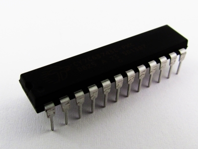
The CGKEYCHIP1 is a 24 pin chip in a DIP (through-hole) package. Four wires connect to the Maximite that include ground, power, and the two PS/2 communication signals (data/clock). You can wire in twelve distinct buttons for the keyboard keys plus three “modifier” buttons.
The CGKEYCHIP1 has two sets of keys that it can transmit:
Set1:
F1
F2
F3
F4
F5
F6
F7
F8
F9
F10
F11
F12
Set2:
Up Arrow
Down Arrow
Left Arrow
Right Arrow
Space Bar
Page Up
Page Down
Enter
End
Home
Tab
Backspace
An input pin on the chip selects between these sets of keys.
The CGKEYCHIP1 runs off of the 5V that the PS/2 connection provides. Both chip grounds should be connected to ground. The pins marked “NoConnect” should not be connected to anything.
Supplied with the CGKEYCHIP1 is a 1.3 kohm resistor that has to be connected from pin 11 to pin 15 for the chip to operate correctly
The PS/2 data signals are open-collector signals. When you connect the GCKEYCHIP1 to a CGCOLORMAX1 there are pull up resistors already on the ColorMax. When you connect to a CGMMSTICK1 and CGVGAKBD1 combination, the CGVGAKBD1 board already has pull up resistors in place for the two PS/2 lines. No additional resistors are needed in this case.

When you connect the CGKEYCHIP1 to just a CGMMSTICK1, you will need to attach two pull-up resistors in order to have the chip function correctly. Each of the two PS/2 lines should be pulled to 5V through a 10 kohm resistor.

The SetSelect input to the CGKEYCHIP1 selects the key set that you wish to use, either set 1 or set 2. Connecting this input directly to 5V will select set 1, while connecting this input to ground selects set 2.
The key inputs are activated by momentary contact to ground. Simple SPST buttons can be used.

Image already added
