Servos are a motor with integrated gears and a control system that allows the position of the shaft to be precisely controlled. MMBasic 5.0 can simultaneously control up to five servos.
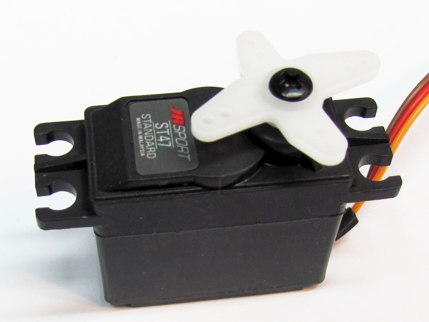
Standard servos allow the shaft to be positioned at various angles, usually between -90 and +90 degrees. Continuous rotation servos allow the rotation of the shaft to be set to various speeds.
The position of the servo is controlled by a pulse which is repeated every 20mS. Generally a pulse width of 0.8mS will position the rotor at -90º, a pulse width of 2.2mS will position it at +90º and 1.5mS will center the rotor. These numbers can vary considerably between manufacturers.
Depending on their size servos can be quite powerful and provide a convenient way for the you to control the mechanical items using MMBasic.
Most servos require a high current 5V power source and have two power leads, red for +V and black for ground. The third wire is the control signal which should be connected to a CGMICROMITE2 (CGMICROKIT) or CGMICROBOARD SERVO I/O pin.
The MMBasic has two servo controllers with the first being able to control up to three servos and the second two servos. To drive the servo you use this command for the servos connected to controller 1:
SERVO 1, 1A, 1B, 1C
And this for servos connected to controller 2:
SERVO 2, 2A, 2B
Where 1A, 1B, 2A, etc are the desired pulse widths in milliseconds for each output of the channel. The output pins are listed on pages 6 and 7 where the outputs are designated as PWM 1A, PWM 1B, PWM 2A, etc (the PWM and SERVO commands are closely related and use the same I/O pins). If you want to control less than this number of servos you can leave the unused output off the list and use that pin as a general purpose I/O.
The pulse width can be specified with a high resolution (about 0.005 mS). For example, the following will position the rotor of the servo connected to channel 1A to near its center:
SERVO 1, 1.525
Following the SERVO command MMBasic will generate a continuous stream of pulses in the background until another servo command is given or the STOP option is used (which will terminate the output).
As another example, the following will swing two servos back and forth alternatively every 5 seconds: These servos should be connected to the outputs PWM 1A and PWM 1B.
DO
SERVO 1, 0.8, 2.2
PAUSE 5000
SERVO 1, 2.2, 0.8
PAUSE 5000
LOOP