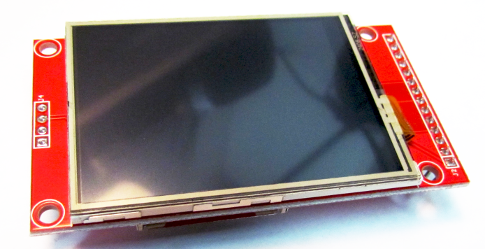
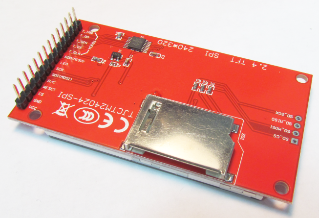
MMBasic version 5.0+ includes support for color LCD display panels using the ILI9341 controller and a SPI interface. These have a 240×320 pixel color TFT display, come in a variety of sizes (2.2”, 2.4″ and 2.8”) and are low cost.
The ILI9341 based displays use an SPI interface and have the following basic specifications:
A 2.2, 2.4 or 2.8 inch display
Resolution of 240 x 320 pixels and a color depth of 262K/65K
A ILI9341 controller with a SPI serial interface


The display pictured above also has a touch sensitive facility which is fully supported by MMBasic. There are versions of this display without the touch controller (the 16-pin IC on the bottom right of the PCB).
The SPI based display controllers share the SPI interface with the touch controller (if present) and the MMBasic program. Sharing the SPI channel is essentially transparent to the BASIC program.
These are the connections required between the LCD display board and a CGMICROMITE2 chip or CGMICROBOARD:
| ILI9341 Display | Signal description | CGMICROMITE2 | CGMICROBOARD |
| T_IRQ | Touch Interrupt | Configurable | uC Pin 14 |
| T_DO | Touch Data Out (MISO) | uC Pin 14 | uC Pin 47 |
| T_DIN | Touch Data In (MOSI) | uC Pin 3 | uC Pin 5 |
| T_CS | Touch Chip Select | Configurable | uC Pin 18 |
| T_CLK | Touch SPI Clock | uC Pin 25 | uC Pin 4 |
| SDO (MISO) | Display Data Out (MISO) | uC Pin 14 | uC Pin 47 |
| LED | Power supply for the backlight | 3.3V | |
| SCK | Display SPI Clock | uC Pin 25 | uC Pin 4 |
| SDI (MOSI) | Display Data In (MOSI) | uC Pin 3 | uC Pin 5 |
| D/C | Display Data/Command Control | Configurable | uC Pin 21 |
| RESET | Display Reset (when pulled low) | Configurable | uC Pin 22 |
| CS | Display Chip Select | Optional – Configurable | uC Pin 23 |
| GND | Ground | Ground | Ground |
| VCC | LCD supply | 3.3V | 3.3V |
Where a connection is listed as “configurable” then you get to pick the specific micocontroller (uC) pin for the purpose. The pin should then be specified with the OPTION LCDPANEL or OPTION TOUCH commands.
J1 on the back side of the ILI9341 LCD display is a jumper that sets the LCD to operate at 3.3V. A solder blob or very short piece of wire should be soldered in place on J1 for 3.3V operation.
The backlight power (the LED connection) should be supplied from the main supply via a current limiting resistor. A typical value for this resistor is 18 ohms which will result in a LED current of about 63mA. The value of this resistor can be varied to reduce the power consumption or to provide a brighter display.
Important: Care must be taken with display panels that share the SPI port between a number of devices (display controller, touch, etc). In this case all the Chip Select signals must be configured in MMBasic or disabled by a permanent connection to 3.3V. If this is not done any Chip Select pins that are not connected will float causing the wrong SPI device to respond to commands on the SPI bus.
Configuring MMBasic to use the ILI9341 LCD Display
To use the display MMBasic must be configured using the OPTION LCDPANEL command which must be entered at the command prompt (not in a program).
The syntax is:
OPTION LCDPANEL ILI9341, orientation, D/C pin, reset pin [,CS pin]
Where:
‘orientation’ can be LANDSCAPE, PORTRAIT, RLANDSCAPE or RPORTRAIT. These can be abbreviated to L, P, RL or RP. The R prefix indicates the reverse or “upside down” orientation.
‘C/D pin’ and ‘reset pin’ are the I/O pins to be used for these functions. Any free pin can be used.
‘CS pin’ can also be any I/O pin but is optional. If a touch controller is not used this parameter can be left off the command and the CS pin on the LCD display wired permanently to ground. If the touch controller is used this pin must then be specified and connected to an I/O pin.
This command only needs to be run once as the parameters are stored in non volatile memory. Every time MMBasic is restarted it will automatically initialize the display ready for use. If the LCD panel is no longer required the command OPTION LCDPANEL DISABLE can be used which will disable the LCD panel feature and return the I/O pins for general use.
To test the display you can enter the command GUI TEST LCDPANEL. You should see an animated display of color circles being rapidly drawn on top of each other. Press any key on the console’s keyboard to stop the test. Important: The above test may not work if the display has a touch controller and the touch controller has not been configured (ie, the touch Chip Select pin is floating). In this case configure the touch controller and then retry GUI TEST LCDPANEL.
NOTE: The CPU speed must be 20MHz or greater.
To verify the LCD panel configuration you can use the command OPTION LIST to list all options that have been set including the configuration of the LCD panel.
For the CGMICROBOARD2, the OPTION LCDPANEL and OPTION TOUCH commands are as follows:
OPTION LCDPANEL ILI9341, L, 21, 22, 23
OPTION TOUCH 18, 14
Touch Support
Most ILI9341 based LCD panels are supplied with a resistive touch sensitive panel and associated controller chip. To use the touch feature in MMBasic the touch controller must first be connected to the CGMICROMITE2/CGMICROBOARD (see the above section for the details) and then configured (see below).
Configuring Touch
To use the touch facility MMBasic must be configured using the OPTION TOUCH command at the command prompt (not in a program). This should be done after the LCD panel has been configured (see above).
The syntax is:
OPTION TOUCH T_CS pin, T_IRQ pin
Where:
‘T_CS pin’ and ‘T_IRQ pin’ are the I/O pins to be used for chip select and touch interrupt respectively (any free pins can be used).
This command only needs to be run once as the parameters are stored in non volatile memory. Every time MMBasic is restarted it will automatically initialize the touch controller.
If the touch facility is no longer required the command OPTION TOUCH DISABLE can be used to disable the touch feature and return the I/O pins for general use (the ‘T_CS pin’ should then be wired to 3.3V to disable the controller).
For the CGMICROBOARD2, the OPTION LCDPANEL and OPTION TOUCH commands are as follows:
OPTION LCDPANEL ILI9341, L, 21, 22, 23
OPTION TOUCH 18, 14
Calibrating the Touch Screen
Before the touch facility can be used it must be calibrated using the GUI CALIBRATE command. This command will present a target in the top left corner of the screen. Using a pointed object such as a stylus press exactly on the centre of the target and hold the stylus down for at least a second. MMBasic will record this location and then continue the calibration by sequentially displaying the target in the other three corners of the screen for touch and calibration.
The calibration routine may warn that the calibration was not accurate. This is just a warning and you can still use the touch feature if you wish but it would be better to repeat the calibration using more care.
Following calibration you can test the touch facility using the GUI TEST TOUCH command. This command will blank the screen and wait for a touch. When the screen is touched a white dot will be placed on the display marking the position on the screen. If the calibration was carried out successfully the dot should be displayed exactly under the location of the stylus on the screen.
To exit the test routine you can press any key on the console’s keyboard.
Touch Functions
To detect if and where the screen is touched you can use the following functions in a BASIC program:
TOUCH(X) – Returns the X coordinate of the currently touched location.
TOUCH(Y) – Returns the Y coordinate of the currently touched location.
Both functions return -1 if the screen is not being touched.
Touch Interrupts
An interrupt can be set on the IRQ pin number that was specified when the touch facility was configured. To detect touch down the interrupt should be configured as INTL (ie, high to low).
For example, if the command OPTION TOUCH 7, 15 was used to configure touch the following program will print out the X and Y coordinates of any touch on the screen:
SETPIN 15, INTL, MyInt
DO : LOOP
SUB MyInt
PRINT TOUCH(X) TOUCH(Y)
END SUB
Note that once set up the interrupt cannot be cancelled (ie, SETPIN 15, OFF will not work).
Leave a Reply