
The “Shield” footprint on a CGCOLORMAX2.
|
Arduino Shield footprint J13 |
|
|
Shield Pins |
Pin from software perspective |
|
D0 |
I/O Pin 21 |
|
D1 |
I/O Pin 22 |
|
D2 |
I/O Pin 23 |
|
D3 |
I/O Pin 24 |
|
D4 |
I/O Pin 25 |
|
D5 |
I/O Pin 26 |
|
D6 |
I/O Pin 27 |
|
D7 |
I/O Pin 28 |
|
D8 |
I/O Pin 29 |
|
D9 |
I/O Pin 30 |
|
D10 |
I/O Pin 31 |
|
D11 |
I/O Pin 32 |
|
D12 |
I/O Pin 33 |
|
D13 |
I/O Pin 34 |
|
A0 |
I/O Pin 35 |
|
A1 |
I/O Pin 36 |
|
A2 |
I/O Pin 37 |
|
A3 |
I/O Pin 38 |
|
A4 |
I/O Pin 39 (see J15 information) |
|
A5 |
I/O Pin 40 (see J14 information) |
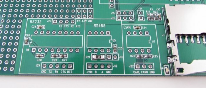
J15 – Shield A4 connection. Connect pins 1-2 to have an I2C connection to SDA on the programming header. Connect 2-3 to connect A4 to I/O Pin 12.
J14 – Shield A5 connection. Connect pins 1-2 to have an I2C connection to SCL on the programming header. Connect 2-3 to connect A5 to I/O Pin 13.
A4/A5 on the Shield connection lead to J15/J14 respectively. A4/A5 can be analog inputs or I2C connections depending on how you may want to use them for the shields that you choose. They are not connected to anything to begin with on the CGCOLORMAX2.
If you wish to use A4/A5 for the I2C interface that MMBasic supports, you will want to connect A4 to I/O Pin 12 (J15 pins 2-3) and connect A5 to I/O Pin 13 (J14 pins 2-3).
If you wish to use A4/A5 for the analog interface that MMBasic supports, you will want to connect J15 pins 1-2 and connect J14 pins 1-2.
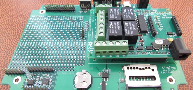
Examples of putting shields on a CGCOLORMAX2