| J9 Pin
/ J13 Pin |
Function | Analog | Digital In | Freq In | Period In | Count In | Digital Out | Open Collector | 5V Tolerant | Additional Function |
| SETPIN:
—> |
1 | 2 | 3 | 4 | 5 | 8 | 9 | |||
| 21 | I/O 1 | Analog In | Digital In | Digital Out | ||||||
| 19 | I/O 2 | Analog In | Digital In | Digital Out | ||||||
| 17 | I/O 3 | Analog In | Digital In | Digital Out | ||||||
| 15 | I/O 4 | Analog In | Digital In | Digital Out | ||||||
| 13 | I/O 5 | Analog In | Digital In | Digital Out | ||||||
| 11 | I/O 6 | Analog In | Digital In | Digital Out | ||||||
| 9 | I/O 7 | Analog In | Digital In | Digital Out | ||||||
| 7 | I/O 8 | Analog In | Digital In | Digital Out | ||||||
| 5 | I/O 9 | Analog In | Digital In | Digital Out | ||||||
| 3 | I/O 10 | Analog In | Digital In | Digital Out | ||||||
| 4 | I/O 11 | Digital In | Freq In | Period In | Count In | Digital Out | O.C. | 5V Tolerant | ||
| 6 | I/O 12 | Digital In | Freq In | Period In | Count In | Digital Out | O.C. | 5V Tolerant | ||
| 8 | I/O 13 | Digital In | Freq In | Period In | Count In | Digital Out | O.C. | 5V Tolerant | ||
| 10 | I/O 14 | Digital In | Freq In | Period In | Count In | Digital Out | O.C. | 5V Tolerant | ||
| 12 | I/O 15 | Digital In | Digital Out | O.C. | 5V Tolerant | Serial 1 Receive | ||||
| 14 | I/O 16 | Digital In | Digital Out | O.C. | 5V Tolerant | Serial 1 Transmit | ||||
| 16 | I/O 17 | Digital In | Digital Out | O.C. | 5V Tolerant | Serial 1 RTS | ||||
| 18 | I/O 18 | Digital In | Digital Out | O.C. | 5V Tolerant | Serial 1 CTS | ||||
| 20 | I/O 19 | Digital In | Digital Out | O.C. | 5V Tolerant | |||||
| 22 | I/O 20 | Digital In | Digital Out | O.C. | 5V Tolerant | |||||
| D0 | I/O 21 | Digital In | Digital Out | O.C. | 5V Tolerant | Serial 2 Receive | ||||
| D1 | I/O 22 | Digital In | Digital Out | O.C. | 5V Tolerant | Serial 2 Transmit | ||||
| D2 | I/O 23 | Digital In | Digital Out | O.C. | 5V Tolerant | |||||
| D3 | I/O 24 | Digital In | Digital Out | O.C. | 5V Tolerant | |||||
| D4 | I/O 25 | Digital In | Digital Out | O.C. | 5V Tolerant | |||||
| D5 | I/O 26 | Digital In | Digital Out | O.C. | 5V Tolerant | |||||
| D6 | I/O 27 | Digital In | Digital Out | O.C. | 5V Tolerant | |||||
| D7 | I/O 28 | Digital In | Digital Out | O.C. | 5V Tolerant | |||||
| D8 | I/O 29 | Digital In | Digital Out | O.C. | 5V Tolerant | |||||
| D9 | I/O 30 | Digital In | Digital Out | O.C. | 5V Tolerant | |||||
| D10 | I/O 31 | Digital In | Digital Out | O.C. | 5V Tolerant | |||||
| D11 | I/O 32 | Digital In | Digital Out | O.C. | 5V Tolerant | |||||
| D12 | I/O 33 | Digital In | Digital Out | O.C. | 5V Tolerant | |||||
| D13 | I/O 34 | Digital In | Digital Out | O.C. | 5V Tolerant | |||||
| A0 | I/O 35 | Analog In | Digital In | Digital Out | ||||||
| A1 | I/O 36 | Analog In | Digital In | Digital Out | ||||||
| A2 | I/O 37 | Analog In | Digital In | Digital Out | ||||||
| A3 | I/O 38 | Analog In | Digital In | Digital Out | ||||||
| A4 | I/O 39 | Analog In | Digital In | Digital Out | ||||||
| A5 | I/O 40 | Analog In | Digital In | Digital Out |
CGCOLORMAX2 Technical Information


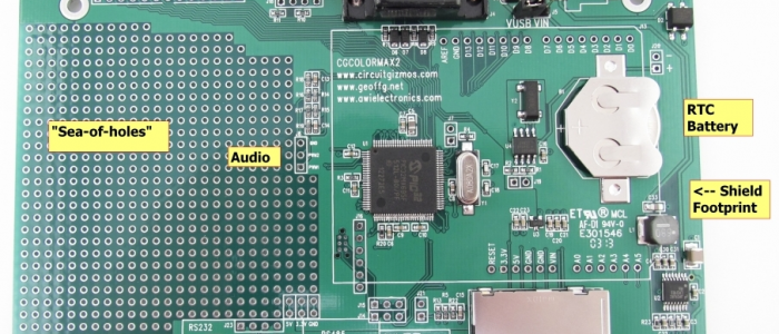
CGCOLORMAX rev 2 I/O callouts.
Typical Digital Output Electrical Characteristics
Output Low Voltage: 0.0 to 0.4V
Output High Voltage: 2.4 to 3.3V
Maximum current draw/sink on any I/O pin: 25mA
Maximum cumulative current draw/sink for all I/O pins: 200mA (150mA derated)
Maximum voltage for 5V tolerant open collector pins: 5.5V
Typical Digital Input Electrical Characteristics
Maximum input voltage, normal pins: 3.6V
Maximum voltage for 5V tolerant input pins: 5.5V
Voltage range for a logic low input: 0.0 to 0.66V
Voltage range for a logic high input: 2.64 to 3.3V
Voltage range for a logic high input – 5V tolerant inputs: 2.64 to 5.5V
Analog input voltage range: 0.0 to 3.3V
CGMMSTICK1 Firmware Update

The CGMMSTICK1 is loaded at the factory with a bootloader and with the version of MMBasic that is current at the time of board production. New versions of MMBasic are released periodically, and the CGMMSTICK1 uses a bootloader that allows for MMBasic update.
Upgrades are done via the USB interface when the boot loader is running.
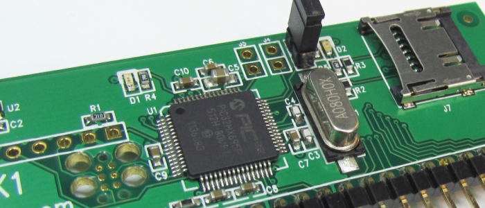
Powering up the CGMMSTICK1 will normally cause MMBasic to run. If a header is in place on J3, then on power up the bootloader will run.

The bootloader jumper in place on a CGMMSTICK.
When the bootloader is running, the green LED on the CGMMSTICK1 will flash on and off. During this time, a PC program can connect through USB to the CGMMSTICK1 for updating firmware. Bootloader.exe will load MMBasic onto a CGMMSTICK1. The program is part of a zip file download from CircuitGizmos. Bootloader.exe runs as a stand-alone program without needing installation.
Updated firmware is available from http://geoffg.net/maximite.html
The CGMMSTICK1 runs the firmware made for the original monochrome Maximite. Download the updated firmware zip file and un-zip it to a directory on your PC.
Firmware Upgrade Steps (CGMMSTICK1)
Start with the CGMMSTICK1 unpowered.
Have the bootloader jumper described above in place on the device while you apply power by connecting the USB cable to your PC. The green CGMMSTICK1 power LED will rapidly flash to indicate that the boot loader is in control. (At this point the bootloader is running and the jumper can be removed.)
The computer should automatically recognize the device and load the appropriate driver. (The CGMMSTICK1 will show up in the Windows Device Manager as a Human Interface Device when connected to the bootloader.)

Bootloader.exe has detected and connected to a CGMMSTICK/CGCOLORMAX in bootloader mode.
Run BootLoader.exe it will automatically detect the device and show the message “Device attached”.
If the Load Hex File button in bootLoader.exe is grayed out it means that the CGMMSTICK1 is not connected or not in boot load mode. Check the USB cable and that the green CGMMSTICK1 LED is flashing.

Bootloader.exe with a firmware hex file loaded.
Click on the Load Hex File button and load the firmware upgrade file. The firmware file will have a .hex extension. An example hex file name might be Maximite_MMBasic_V4.3.hex.

Bootloader.exe erasing the CGMMSTICK/CGCOLORMAX firmware.
After the firmware hex file is loaded into bootloader.exe, press the Program Device button.
Bootloader.exe will erase the old firmware first. This isn’t a full erase of the CGMMSTICK1 chip, as a full erase would also erase the bootloader and that needs to stay on the chip. Everything BUT the bootloader is erased, which means that the contents of the on-chip A: drive is also completely cleared.

After erasing, bootloader.exe will program the new firmware to the CGMMSTICK/CGCOLORMAX.
Once erased, bootloader will program the new firmware to the CGMMSTICK1. There is a progress bar that shows the progress of this programming operation. Immediately after programming bootloader.exe will double-check to make sure that the firmware was correctly loaded with a verification step.
The entire programming and verification process should take only about a minute.

Programming finished.
After verification the green CGMMSTICK1 power LED will flash slowly. This indicates that the new firmware on the CGMMSTICK1 is completely programmed.
Remove the power connection from the CGMMSTICK1. Make sure that the J3 jumper has also been removed.
Power the CGMMSTICK1 again and the updated MMBasic firmware will run.
- « Previous Page
- 1
- …
- 12
- 13
- 14
- 15
- 16
- …
- 22
- Next Page »