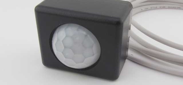
Added the GCUSBPIRTINY1 to products. This tiny enclosure is 1″ by 1.25″ by 1.5″. The cable exits the back at the bottom.
Electronic Products for Creative Minds
CircuitGizmos now offers quantity discounts on many of our popular products!


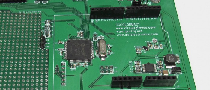
CGCOLORMAX powered through USB. Tethered to the PC through the USB port. CGCOLORMAX1 shown here, but the same thing applies to the CGCOLORMAX2.
Before you use the USB interface on the CGCOLORMAX you will need to install the USB driver for the Maximite, so that the CGMMSTICK/CGCOLORMAX will appear to your PC as a serial port. The PC driver and instructions are included with the MMIDE download.
The driver is needed if you use the USB connection to your PC. The driver makes the board appear to the PC as a serial port.
Once you have the drivers installed for the CGCOLORMAX, plugging in the USB connection will create a new serial port on your PC. You can use various serial terminal programs to connect to that new serial port and communicate with the CGCOLORMAX. You can also use the Maximite Integrated Development Environment – MMIDE – to develop CGCOLORMAX projects.
On the CGCOLORMAX1 the power selection header should have a jumper in place on the left two pins. That is to say that the jumper in J5 would be in the “VUSB” position. The 5V from USB would then power the board.
On the CGCOLORMAX1 the power selection header has a total of 4 pins. On the CGCOLORMAX2 the power selection header has a total of three pins. Middle pin and left pin would be VUSB.

CGCOLORMAX powered through the 12V power connections. Keyboard and VGA connections allow the board to be a stand-alone computer. CGCOLORMAX1 shown here, but the same thing applies to the CGCOLORMAX2.
If you don’t want to use the CGCOLORMAX tethered to your PC but want to use it as a stand-alone computer with a keyboard and VGA display, you can power the board through the 12V power input connection and connect a VGA display and PS/2 keyboard.
On the CGCOLORMAX1 the power selection header should have a jumper in place on the right two pins (of the 4 total). That is to say that the jumper in J5 would be in the “VIN” position. The 8V – 18V DC from an external supply would then power the board.
On the CGCOLORMAX1 the power selection header has a total of 4 pins. On the CGCOLORMAX2 the power selection header has a total of three pins. Middle pin and right pin would be VIN.