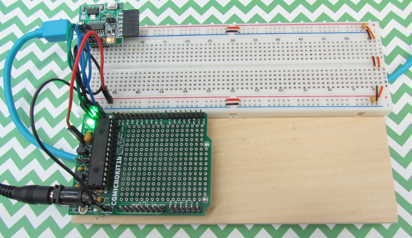
The CGMICROKIT1 can be at the heart of a simple, but powerful electronics test setup. Pair the CGMICROKIT1 with a single solderless breadboard, a USB/serial interface to the PC, and a suitable power supply for a convenient test bed for proving out small circuitry and experimenting with electronic devices.
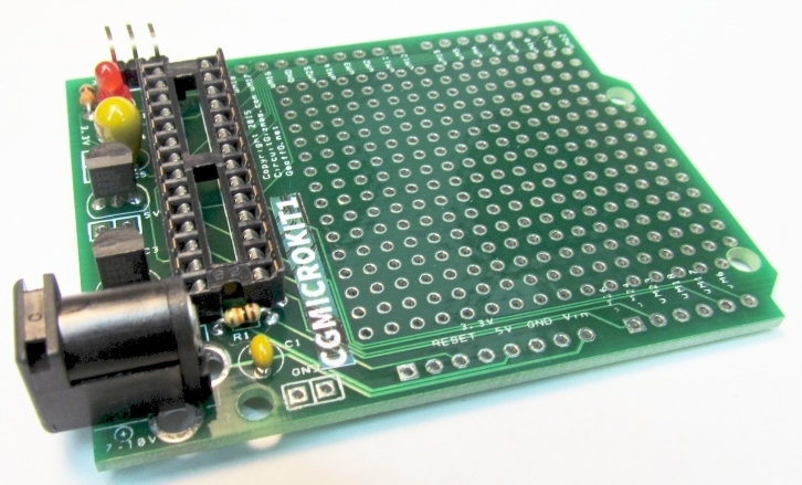
Assemble the CGMICROKIT1 as per the instructions. Populate it with the CGMICROMITE2 with its powerful built-in language interpreter. Also add .1″ pin headers in rows for the data connections, ground, and power connections.
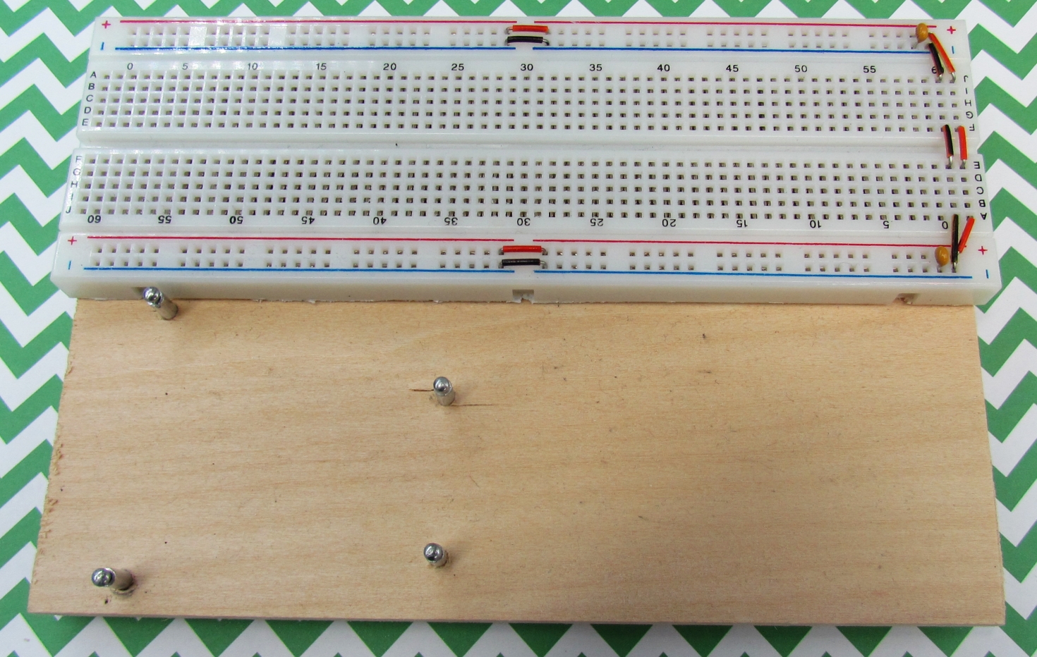
A solderless breadboard mounted on a 1/4″ thick piece of hobby wood is the base for this setup. The wood is approximately 6″ by 4″. There are four adhesive felt feet on the bottom of the wood to protect the desktop. There are four metal posts on the wooden base for where the CGMICROKIT1 mounts. They were made from long rivets, but the same type of mount could be made from #4 machine screws.
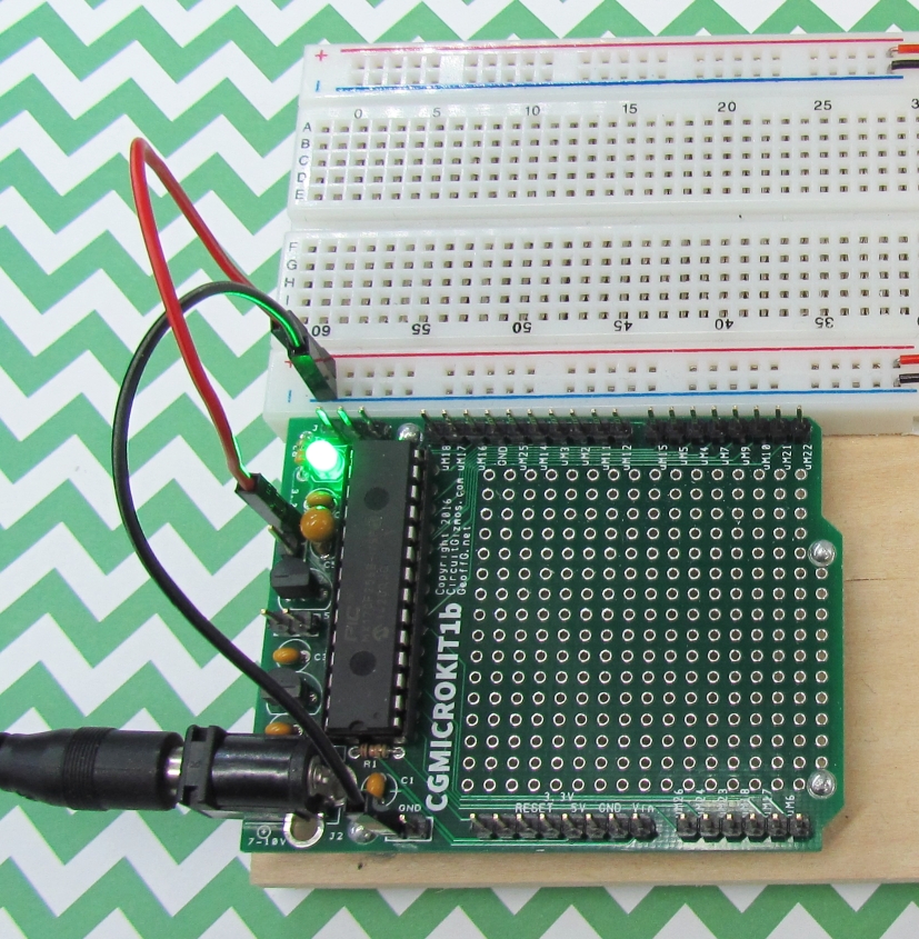
The CGMICROKIT1 mounts into place and jumpers from that PCB provide ground and power connections to the solderless breadboard. Note that the CGMICROKIT can provide 5.0V and 3.3V to the circuits on the solderless breadboard. In the photos here, it is 3.3V that is connected to the solderless breadboard.
Power to the CGMICROKIT1 can be obtained by using a 9V battery and the adaptor shown in the picture, or an AC/DC adaptor (wall wart) with 7-12V output can be used.
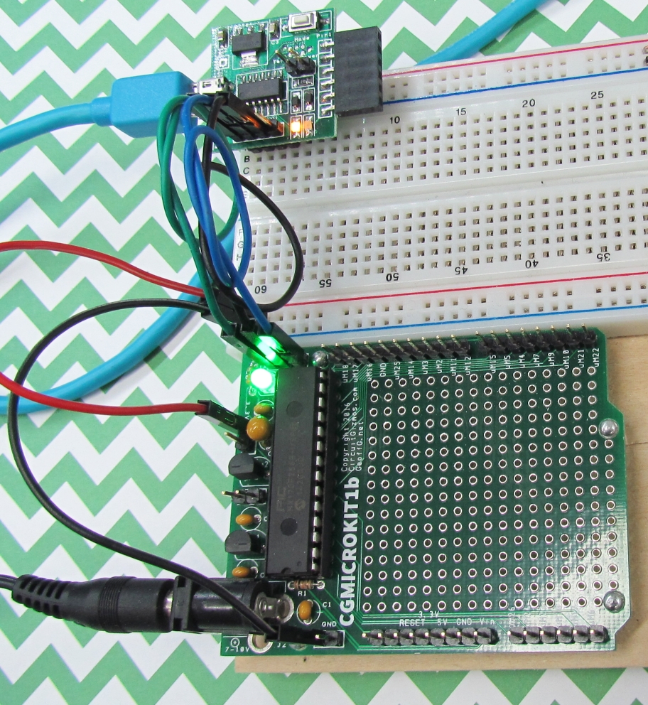
This photo shows the use of a wall wart to provide power to the test setup.
Communication/programming of the microcontroller on the CGMICROKIT1 is done through serial lines. These serial lines are 3.3V digital levels. A USB/serial adaptor is used to allow a PC to communicate with the CGMICROKIT1. The CGUSBSERPRG1 is used as it has a 3.3V data interface. Ground and the pairs of data lines are connected between the two devices. To the PC, the CGMICROKIT1 appears as a USB serial port.
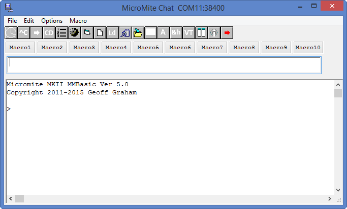
The development program called MMEDIT (http://www.c-com.com.au/MMedit.htm) runs on a PC and makes it easy to program for the microcontroller on the CGMICROKIT1. In the photo, MMEDIT has attached to the USB serial port associated with the test setup and the welcome message is shown in MMEDIT’s chat window. Programs are written in the editor of MMEDIT and then easily sent via USB serial to the CGMICROKIT1 to run.
As an example of a very simple test circuit and program, an LED will be connected to I/O pin #6 and enabled.
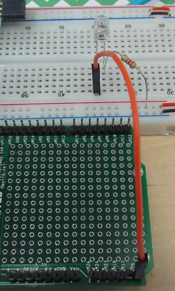
The LED is placed on the solderless breadboard. One pin of the LED is connected to I/O pin #6 (labeled uM6 on the CGMICROKIT1) with the orange jumper wire. The other pin of the LED connects to 3.3V through a current limiting 220Ω resistor.
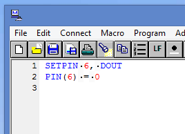
The simple program in the editor of MMEDIT is only two lines. The first line sets I/O pin #6 to be a digital output. To turn on the LED the output must be set low (the other pin of the LED is pulled high). When downloaded to the CGMICROKIT and run, the LED lights up.
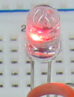
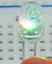
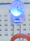
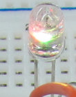
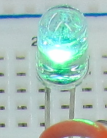
This was a bit of a FANCY PARTY LED, in that when power is applied to the LED, it doesn’t just shine in one color, it blinks and flashes and cycles through a bunch of colors.

I have a CGMicrokit1.
Instead of powering it with 9V via the jack, can I safely apply +5V to one of the 5V pins?
I have 5V available from my USB to Serial converter.
Yes it can be powered from 5V.