CircuitGizmos

Electronic Products for Creative Minds

  • Home
  • Gizmo Store/Products
  • Documentation/Datasheets
  • Projects/Libraries
  • GizmoBlog
  • Services/Contact
    • Design
    • Contact Gizmo!
  • Your Gizmo Cart
    • Your Account

CGMMSTICK Setup

CGMMSTICK Setup


CGMMSTICK1 with the row of 30 connections used to interface to electrical circuits.

The CGMMSTICK that you have purchased has a row of 30 connections running along one edge as solderable wire points.

These connections are used for interfacing to your circuits. If you have a project where you would like to connect your circuits directly to the CGMMSTICK, the J1 row of 30 pins can have 20 gauge wire soldered directly to the gold-coated pins.

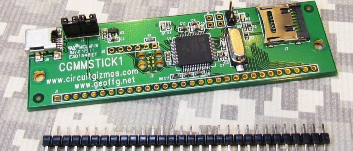
CGMMSTICK1 with a 30 pin header.

If you intend to use the CGMMSTICK with solderless breadboards, as the projects in this document demonstrate, then a 30 pin header is available from CircuitGizmos to solder in place.

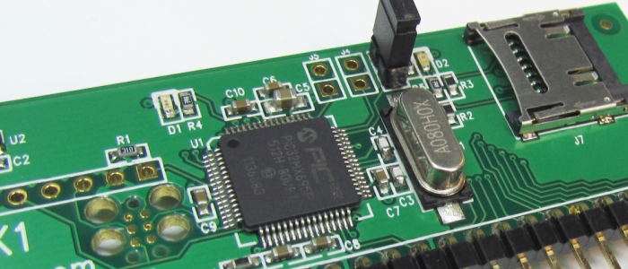
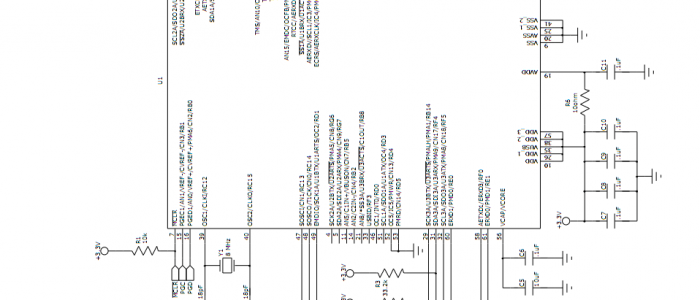
Some of the signals that you can connect to to on the CGMMSTICK1.

Before you use the USB interface on the CGMMSTICK you will need to install the USB driver for the Maximite, so that the CGMMSTICK will appear to your PC as a serial port. The PC driver and instructions are included with the MMIDE download.

The MMIDE download is available for free from https://www.circuitgizmos.com More information about running MMIDE (there is no installation, just copied files) is described later.

Once you have the drivers installed for the CGMMSTICK , plugging in the USB connection will create a new serial port on your PC. You can use various serial terminal programs to connect to that new serial port and communicate with the CGMMSTICK. You can also use the Maximite Integrated Development Environment – MMIDE – to develop CGMMSTICK projects.

The CGVGAKBD provides VGA and keyboard connectors for the CGMMSTICK.

If you don’t want to use the CGMMSTICK tethered to your PC but want to use it as a stand-alone computer with a keyboard and VGA display, you can add the CGVGAKBD board to your CGMMSTICK to make a stand-alone computer.

A CGVGAKBD used with a CGMMSTICK. Both boards are mounted on a protoboard. Underneath the boards are wired together pin 1 to pin 1, 2 to 2, etc.

Some of the lines on the 30 pins of the CGMMSTICK are meant as signal lines for VGA and keyboard connections.

You can get away with wiring pins 1-10 on both devices together (A connection from pin 1 on the CGMMSTICK to pin 1 on the CGVGAKBD. Another from pin 2 to pin 2, etc.) Or you can just wire all 30 lines from one board to the next. Whatever is convenient.

You need to provide 5V DC at at least 160 mA to power this setup. 5V from an external supply (5V regulated wall wort will work) connects to the supply pins of the 30 pin J1.

The back side of a CGVGAKBD. Note pin 1 of J1 on the far left.

If you look at the back side of the CGVGAKBD you will see the J1 header which is meant to be a one-to-one duplicate of the J1 header on the CGMMSTICK.

Also note J5 which duplicates 20 of the J1 lines. These are the I/O lines that MMBasic can control. There is a small “sea-of-holes” on the board – a small prototyping area where you can add your own circuit. Perhaps something like a D/A converter, a relay, or small buttons could be wired from that area to some I/O lines on J5.

A CGMMSTICK/CGMMVGAKBD combination as a stand-alone computer.

Once wired to a CGMMSTICK, this board lets you attach a VGA display for monochrome video. As an alternate display, you could also attach a composite monitor to the yellow RCA connector (requires a jumper on the CGMMSTICK board).

A keyboard can be connected to the PS/2 keyboard jack for input to the CGMMSTICK.

In the photo above 5V needed to power this stand-alone setup is provided through the USB connection. There is no “data” USB connection to the PC in this case – it was convenient for the photo to use a USB cell phone charger that provides 5V at 500 mA.


CGMMSTICK1 Firmware Update

CGMMSTICK1 Firmware Update

The CGMMSTICK1 is loaded at the factory with a bootloader and with the version of MMBasic that is current at the time of board production. New versions of MMBasic are released periodically, and the CGMMSTICK1 uses a bootloader that allows for MMBasic update.

Upgrades are done via the USB interface when the boot loader is running.

Powering up the CGMMSTICK1 will normally cause MMBasic to run. If a header is in place on J3, then on power up the bootloader will run.

The bootloader jumper in place on a CGMMSTICK.

When the bootloader is running, the green LED on the CGMMSTICK1 will flash on and off. During this time, a PC program can connect through USB to the CGMMSTICK1 for updating firmware. Bootloader.exe will load MMBasic onto a CGMMSTICK1. The program is part of a zip file download from CircuitGizmos. Bootloader.exe runs as a stand-alone program without needing installation.

Updated firmware is available from http://geoffg.net/maximite.html

The CGMMSTICK1 runs the firmware made for the original monochrome Maximite. Download the updated firmware zip file and un-zip it to a directory on your PC.

Firmware Upgrade Steps (CGMMSTICK1)

Start with the CGMMSTICK1 unpowered.

Have the bootloader jumper described above in place on the device while you apply power by connecting the USB cable to your PC. The green CGMMSTICK1 power LED will rapidly flash to indicate that the boot loader is in control. (At this point the bootloader is running and the jumper can be removed.)

The computer should automatically recognize the device and load the appropriate driver. (The CGMMSTICK1 will show up in the Windows Device Manager as a Human Interface Device when connected to the bootloader.)

Bootloader.exe has detected and connected to a CGMMSTICK/CGCOLORMAX in bootloader mode.

Run BootLoader.exe it will automatically detect the device and show the message “Device attached”.

If the Load Hex File button in bootLoader.exe is grayed out it means that the CGMMSTICK1 is not connected or not in boot load mode. Check the USB cable and that the green CGMMSTICK1 LED is flashing.

Bootloader.exe with a firmware hex file loaded.

Click on the Load Hex File button and load the firmware upgrade file. The firmware file will have a .hex extension. An example hex file name might be Maximite_MMBasic_V4.3.hex.

Bootloader.exe erasing the CGMMSTICK/CGCOLORMAX firmware.

After the firmware hex file is loaded into bootloader.exe, press the Program Device button.

Bootloader.exe will erase the old firmware first. This isn’t a full erase of the CGMMSTICK1 chip, as a full erase would also erase the bootloader and that needs to stay on the chip. Everything BUT the bootloader is erased, which means that the contents of the on-chip A: drive is also completely cleared.

After erasing, bootloader.exe will program the new firmware to the CGMMSTICK/CGCOLORMAX.

Once erased, bootloader will program the new firmware to the CGMMSTICK1. There is a progress bar that shows the progress of this programming operation. Immediately after programming bootloader.exe will double-check to make sure that the firmware was correctly loaded with a verification step.

The entire programming and verification process should take only about a minute.

Programming finished.

After verification the green CGMMSTICK1 power LED will flash slowly. This indicates that the new firmware on the CGMMSTICK1 is completely programmed.

Remove the power connection from the CGMMSTICK1. Make sure that the J3 jumper has also been removed.

Power the CGMMSTICK1 again and the updated MMBasic firmware will run.


CGMMSTICK1 Schematic

CGMMSTICK1 Schematic


  • 1
  • 2
  • 3
  • Next Page »

A Ton of Documentation

Open all | Close all

Projects made by Gizmo, Friends, and Members

open all | close all

Recent GizmoBlog Musings

  • Altair 8800 using a ColorMax!
  • Re-energizing the ColorMax, Pt. 3

Visit us!

  • Facebook

Electronic Products for Creative Minds

CircuitGizmos is your source for electronic products that help you create your embedded projects. Here at CircuitGizmos.com you will find a friendly store filled with creative products and all of the documentation that you need to use these gizmos.

We create devices that we believe make electronics fun, but we also know that our products are used for professional designs. For decades we have designed products for commercial, military, and medical industries. Our gizmos here are great for engineers and hobbyists alike.

Copyright © 2008+ CircuitGizmos, L.L.C. All rights reserved

Image already added

Recently Viewed Products

Copyright © 2025 · Generate Pro Theme on Genesis Framework · WordPress · Log in