The power select jumper (J5) near to the USB jack and to input power selects powering the board from either the USB connector or from the input power jack. Place a header on VUSB to power the board from USB. Move the header to VIN to power the board from the input power connector.
The USB connection provides 5V to the board. The USB hub that you use with this board should supply at least 250mA. Typical powered hubs provide 500mA. 3.3V is regulated internally to power the internal circuitry.
Input voltage (J6) is 8-18VDC. The power supply should be rated at being able to supply a minimum of 250 milliamps. 5V is regulated from this, and 3.3V is then regulated from 5V.
The 5V regulator can regulate 700mA for on-board circuits. The 3.3V supply can regulate 200mA (subtracted from the 5V 700mA). Existing 3.3V circuits consume 150mA on the 3.3V line. This leaves 3.3V 50mA, and 5V 500mA for user circuitry.

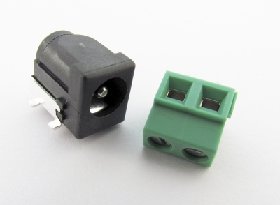
Barrel jack and screw terminal.

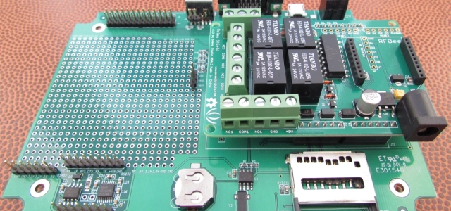
The CGCOLORMAX2 power input populated with the screw terminal connector.
J6 can be populated with either the supplied screw terminal, or the 5.5mm/2.1mm barrel jack. When using a DC supply with the CGCOLORMAX2, the board circuitry takes care of polarity. The barrel connector used can be center positive or center negative. Positive/negative can be exchanged on the screw connections, too.

The barrel jack installed on a CGCOLORMAX.
The CGCOLORMAX2 can be powered by a PC USB connection, but it can also be powered through the USB connector by using a wall-wart or car power adapter that provides +5V via a USB mini-B plug. Things such as cell phone chargers for AC (wall) use, or car cigarette lighter chargers will work if they provide enough current and a regulated +5V.


