CircuitGizmos

Electronic Products for Creative Minds

  • Home
  • Gizmo Store/Products
  • Documentation/Datasheets
  • Projects/Libraries
  • GizmoBlog
  • Services/Contact
    • Design
    • Contact Gizmo!
  • Your Gizmo Cart
    • Your Account

CGCOLORMAX Setup

CGCOLORMAX Setup

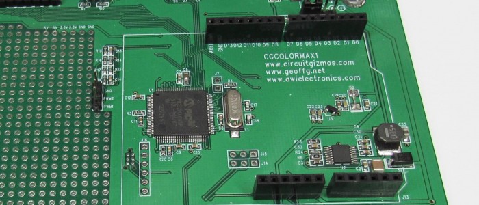
CGCOLORMAX powered through USB. Tethered to the PC through the USB port. CGCOLORMAX1 shown here, but the same thing applies to the CGCOLORMAX2.

Before you use the USB interface on the CGCOLORMAX you will need to install the USB driver for the Maximite, so that the CGMMSTICK/CGCOLORMAX will appear to your PC as a serial port. The PC driver and instructions are included with the MMIDE download.

The driver is needed if you use the USB connection to your PC. The driver makes the board appear to the PC as a serial port.

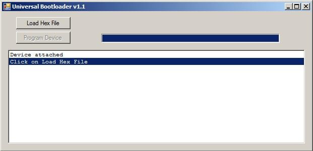
Once you have the drivers installed for the CGCOLORMAX, plugging in the USB connection will create a new serial port on your PC. You can use various serial terminal programs to connect to that new serial port and communicate with the CGCOLORMAX. You can also use the Maximite Integrated Development Environment – MMIDE – to develop CGCOLORMAX projects.

On the CGCOLORMAX1 the power selection header should have a jumper in place on the left two pins. That is to say that the jumper in J5 would be in the “VUSB” position. The 5V from USB would then power the board.

On the CGCOLORMAX1 the power selection header has a total of 4 pins. On the CGCOLORMAX2 the power selection header has a total of three pins. Middle pin and left pin would be VUSB.

CGCOLORMAX powered through the 12V power connections. Keyboard and VGA connections allow the board to be a stand-alone computer. CGCOLORMAX1 shown here, but the same thing applies to the CGCOLORMAX2.

If you don’t want to use the CGCOLORMAX tethered to your PC but want to use it as a stand-alone computer with a keyboard and VGA display, you can power the board through the 12V power input connection and connect a VGA display and PS/2 keyboard.

On the CGCOLORMAX1 the power selection header should have a jumper in place on the right two pins (of the 4 total). That is to say that the jumper in J5 would be in the “VIN” position. The 8V – 18V DC from an external supply would then power the board.

On the CGCOLORMAX1 the power selection header has a total of 4 pins. On the CGCOLORMAX2 the power selection header has a total of three pins. Middle pin and right pin would be VIN.


CGCOLORMAX Composite Output

CGCOLORMAX Composite Output

On the CGCOLORMAX Maximite composite video (in monochrome not color) can be accessed via the VGA connector using the following connections:


Composite display circuit.

The screen resolution for composite display in PAL (default) mode is 304 horizontal, and 216 vertical. Screen resolution in NTSC is 304 horizontal, and 180 vertical.

Use CONFIG COMPOSITE to set either PAL or NTSC. NTSC is used for composite video in the United States.

CGCOLORMAX2 Firmware Update

CGCOLORMAX2 Firmware Update

The CGCOLORMAX2 is loaded at the factory with a bootloader and with the version of MMBasic that is current at the time of board production. New versions of MMBasic are released periodically, and the CGCOLORMAX2 uses a bootloader that allows for MMBasic update.

Upgrades are done via the USB interface when the boot loader is running.

Powering up the CGCOLORMAX2 will normally cause MMBasic to run. If a wire jumper is in place on J7, then on power up the bootloader will run.

A bootloader wire jumper in place on a CGCOLORMAX2.

The jumper can be any simple thin wire momentarily held in place to electrically connect both contacts of J7. Even a bare paperclip would work.

When the bootloader is running, the green LED on the CGCOLORMAX2 will flash on and off. During this time, a PC program can connect through USB to the CGCOLORMAX2 for updating firmware. Bootloader.exe will load MMBasic onto a CGCOLORMAX2. The program is part of a zip file download from CircuitGizmos. Bootloader.exe runs as a stand-alone program without needing installation.

Firmware Upgrade Steps

Start with the CGCOLORMAX2 unpowered.

Have the bootloader jumper wire described above in place on the device while you apply power by connecting the USB cable to your PC. The green CGCOLORMAX2 power LED will rapidly flash to indicate that the boot loader is in control. (At this point the bootloader is running and the jumper can be removed.)

The computer should automatically recognize the device and load the appropriate driver. (The CGCOLORMAX2 will show up in the Windows Device Manager as a Human Interface Device when connected to the bootloader.)

Bootloader.exe has detected and connected to a CGMMSTICK/CGCOLORMAX in bootloader mode.

Run BootLoader.exe it will automatically detect the device and show the message “Device attached”.

If the Load Hex File button in bootLoader.exe is grayed out it means that the CGMMSTICK1 is not connected or not in boot load mode. Check the USB cable and that the green CGCOLORMAX2 LED is flashing.

Bootloader.exe with a firmware hex file loaded.

Click on the Load Hex File button and load the firmware upgrade file. The firmware file will have a .hex extension.

An example hex file name might be Maximite_MMBasic_V4.3.hex.

Bootloader.exe erasing the CGMMSTICK/CGCOLORMAX firmware.

After the firmware hex file is loaded into bootloader.exe, press the Program Device button.

Bootloader.exe will erase the old firmware first. This isn’t a full erase of the CGCOLORMAX2 chip, as a full erase would also erase the bootloader and that needs to stay on the chip. Everything BUT the bootloader is erased, which means that the contents of the on-chip A: drive is also completely cleared.

After erasing, bootloader.exe will program the new firmware to the CGMMSTICK/CGCOLORMAX.

Once erased, bootloader will program the new firmware to the CGCOLORMAX2. There is a progress bar that shows the progress of this programming operation. Immediately after programming bootloader.exe will double-check to make sure that the firmware was correctly loaded with a verification step.

The entire programming and verification process should take only about a minute.

Programming finished.

After verification the green CGCOLORMAX2 power LED will flash slowly. This indicates that the new firmware on the CGCOLORMAX2 is completely programmed.

Remove the power connection from the CGCOLORMAX2. Make sure that the J7 jumper wire has also been removed.

Power the CGCOLORMAX2 again and the updated MMBasic firmware will run.


  • 1
  • 2
  • 3
  • 4
  • Next Page »

A Ton of Documentation

Open all | Close all

Projects made by Gizmo, Friends, and Members

open all | close all

Recent GizmoBlog Musings

  • Altair 8800 using a ColorMax!
  • Re-energizing the ColorMax, Pt. 3

Visit us!

  • Facebook

Electronic Products for Creative Minds

CircuitGizmos is your source for electronic products that help you create your embedded projects. Here at CircuitGizmos.com you will find a friendly store filled with creative products and all of the documentation that you need to use these gizmos.

We create devices that we believe make electronics fun, but we also know that our products are used for professional designs. For decades we have designed products for commercial, military, and medical industries. Our gizmos here are great for engineers and hobbyists alike.

Copyright © 2008+ CircuitGizmos, L.L.C. All rights reserved

Image already added

Recently Viewed Products

Copyright © 2023 · Generate Pro Theme on Genesis Framework · WordPress · Log in